DIY: B5 Control Arms and Tie Rod End Assemblies, Part 3: Upper Control Arms
#1
 08-25-2011, 03:05 PM

Alright, alright.
In part 1, we prepared your car for replacement. In part 2, we went through the steps to replace the inner and outer tie rod end assemblies.
In part 3, it's time to tackle those upper control arms, along with the dreaded "pinch bolt" that has been a source of many frustrated do-it-yourselfers. With a little bit of preparation, lots of mapp gas heat and plenty of violence, this job is going to be very rewarding.
Remember, always wear your safety goggles when doing any hammering, or when you're under the car.
Are you ready to have some fun? Let's do this!
Step 19. First things first. Begin by spraying a generous amount of PB Blaster onto the pinch bolt and it's nut, as well as in the gaps in the spindle. If you've read parts 1 & 2, you know that I've been telling you to do this for multiple days in advance in order for it to seep into the rust.

While the PB Blaster is soaking in, loosen up the bolts that connect the upper control arms to the shock housing. The bolt head and nut are 16mm.

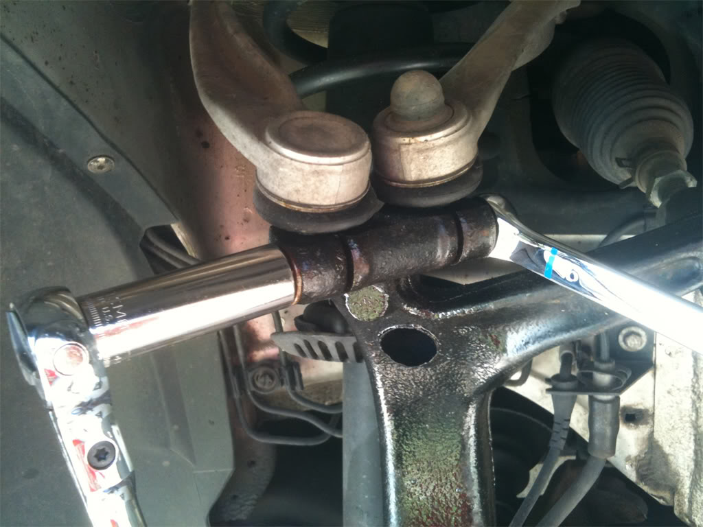
Step 20. Since the pinch bolt is usually the most difficult bolt to loosen and remove in the entire job, give yourself a better chance at removing it the first time by hitting it with some mapp gas heat. Grab your torch and heat up the pinch bolt area of the spindle, along with the nut. When it's good and hot, attach your 16mm socket to the pinch bolt nut, and your 16mm wrench to the bolt head on the other side. Turn counter-clockwise to loosen the bolt. Come on, baby, break loose for us!
Step 21. If the gods of pinch bolts were kind to you, the nut should be loose now. Unscrew the nut until it's at the end of the pinch bolt, but still on the bolt. You're going to use this nut to hammer on with your 4lb sledge hammer to get the pinch bolt moving. Before you start hammering on the pinch bolt, shock the spindle by whacking it with the hammer where the pinch bolt lives.

Then, take a large flat head screwdriver or small pry bar, and try to wedge it into the open spaces on the side of the spindle where the pinch bolt lives. After prying that apart for a bit, hit that area with the mapp gas torch again.
Now take the hammer, and hit that nut like there's no tomorrow. Heat & violence should win the game here. As shown in the pic below, the pinch bolt has started to move. Keep pounding away until the bolt is level with the hole in the spindle.

Next, take a punch and align it onto the pinch bolt.

Hammer away at the punch until that pinch bolt is your beyotch and she pops out of the spindle and onto the floor.
Success!

Now, if for some reason that pinch bolt is not out by this time, you either need to hit the gym to grow some muscles, or you didn't heat up the spindle enough. Try heating the spindle up again, and this time make it red hot!
If it still won't budge, then you want to look into borrowing a friend's air powered hammer in order to use superior brute force. If that doesn't work, then it's time to either drill it out, or buy a used spindle. From everything I've read, it's a bigger PITA to try to drill the pinch bolt out than it is to purchase a used spindle online and just replace it. If you do go the route of buying a used or new spindle, make sure to order one that already has a wheel bearing installed.
Step 22. Now that the pinch bolt is out, we can remove the control arm nipples from the spindle. You can either use the fancy tool from the Front End Service Kit that I showed you in part 2, or you can use the short screwdriver & hammer method and tap them out this way. As a review, here is the pic from the tie rod end removal showing the tool I used.

Here's a pic or the upper control arms completely freed from the spindle. Notice the grooves in the pic. When you install the new control arms, these grooves must line up with where the pinch bolt is going to pass through them in the spindle, otherwise the pinch bolt won't be able to travel through the entire spindle. So when you pound the nipples back into the spindle, make sure to get them down far enough so that the grooves are lined up in the hole.

Step 23. At this point, you can remove the upper front control arm by unscrewing the bolt that you loosed before. You won't be able to remove the upper rear control arm, though, because there's not enough room to get the bolt out of the shock housing. In step 24, you're going to remove the shock housing from the car, allowing you ease of removal of that last control arm, and easy installation of both new upper control arms.
Step 24. Open your hood and look for three 16mm bolts that hold the shock tower to the car. On the passenger side, if you have the 2.8L V6 engine like I do, you'll have to remove this cover...

and this strip of rubber and cover.

Now, we see our three bolts.

That little green module is in the way of one of the bolts. No problem, you can just wiggle it forward to free it from the two little plastic arms holding it in place. When free, move it to the side.

Now you may proceed to remove the bolts using a 16mm socket, or a 16mm box end wrench. Since I'm lazy by nature, instead of removing the cabin air filter cover to get at the bolt closest to the firewall, I opted to use a 16mm box end wrench on it instead of a socket.
Step 25. One last thing to do before you can remove the entire shock tower. You need to remove the strut bolt from the lower front control arm.
The 18mm nut on mine looked pretty rusty, so I hit it with some mapp gas heat before I attempted to remove it.

Next, put the socket on the nut, and an 18mm box end wrench on the bolt head on the other side of the control arm, and remove it.

Step 26. Remove the entire shock tower and place it on the ground. From here, proceed to unbolt the remaining upper control arm.

On the passenger side, I had no trouble, since the bolt head was pointing toward the front of the vehicle. But on the driver's side, the bolt head was point toward the rear of the vehicle, which means that the bolt ran into the lower rear control arm and before it was out of the lower front control arm. Here's a pic of this dilemma.

In my case, I had to wait to remove this bolt until I dropped the lower rear control arm out of the spindle. I won't spend time on that in this thread, as the lower control arms will be dealt with in part 4. Maybe I was just unlucky and your bolt head will point toward the front of the vehicle on both sides.
Alright, we're done with part 3! Installing the upper control arms is a snap, so I won't spend any time talking about it in a thread as large as this one is already.
In our final installment, part 4, you are going to tackle the lower control arms. I don't want to give too many surprises away, but there is one PITA when dealing with the passenger side lower rear control arm. But other than that, it's not bad at all.
In part 1, we prepared your car for replacement. In part 2, we went through the steps to replace the inner and outer tie rod end assemblies.
In part 3, it's time to tackle those upper control arms, along with the dreaded "pinch bolt" that has been a source of many frustrated do-it-yourselfers. With a little bit of preparation, lots of mapp gas heat and plenty of violence, this job is going to be very rewarding.
Remember, always wear your safety goggles when doing any hammering, or when you're under the car.
Are you ready to have some fun? Let's do this!
Step 19. First things first. Begin by spraying a generous amount of PB Blaster onto the pinch bolt and it's nut, as well as in the gaps in the spindle. If you've read parts 1 & 2, you know that I've been telling you to do this for multiple days in advance in order for it to seep into the rust.
While the PB Blaster is soaking in, loosen up the bolts that connect the upper control arms to the shock housing. The bolt head and nut are 16mm.
Step 20. Since the pinch bolt is usually the most difficult bolt to loosen and remove in the entire job, give yourself a better chance at removing it the first time by hitting it with some mapp gas heat. Grab your torch and heat up the pinch bolt area of the spindle, along with the nut. When it's good and hot, attach your 16mm socket to the pinch bolt nut, and your 16mm wrench to the bolt head on the other side. Turn counter-clockwise to loosen the bolt. Come on, baby, break loose for us!
Step 21. If the gods of pinch bolts were kind to you, the nut should be loose now. Unscrew the nut until it's at the end of the pinch bolt, but still on the bolt. You're going to use this nut to hammer on with your 4lb sledge hammer to get the pinch bolt moving. Before you start hammering on the pinch bolt, shock the spindle by whacking it with the hammer where the pinch bolt lives.
Then, take a large flat head screwdriver or small pry bar, and try to wedge it into the open spaces on the side of the spindle where the pinch bolt lives. After prying that apart for a bit, hit that area with the mapp gas torch again.
Now take the hammer, and hit that nut like there's no tomorrow. Heat & violence should win the game here. As shown in the pic below, the pinch bolt has started to move. Keep pounding away until the bolt is level with the hole in the spindle.
Next, take a punch and align it onto the pinch bolt.
Hammer away at the punch until that pinch bolt is your beyotch and she pops out of the spindle and onto the floor.
Success!
Now, if for some reason that pinch bolt is not out by this time, you either need to hit the gym to grow some muscles, or you didn't heat up the spindle enough. Try heating the spindle up again, and this time make it red hot!
If it still won't budge, then you want to look into borrowing a friend's air powered hammer in order to use superior brute force. If that doesn't work, then it's time to either drill it out, or buy a used spindle. From everything I've read, it's a bigger PITA to try to drill the pinch bolt out than it is to purchase a used spindle online and just replace it. If you do go the route of buying a used or new spindle, make sure to order one that already has a wheel bearing installed.
Step 22. Now that the pinch bolt is out, we can remove the control arm nipples from the spindle. You can either use the fancy tool from the Front End Service Kit that I showed you in part 2, or you can use the short screwdriver & hammer method and tap them out this way. As a review, here is the pic from the tie rod end removal showing the tool I used.
Here's a pic or the upper control arms completely freed from the spindle. Notice the grooves in the pic. When you install the new control arms, these grooves must line up with where the pinch bolt is going to pass through them in the spindle, otherwise the pinch bolt won't be able to travel through the entire spindle. So when you pound the nipples back into the spindle, make sure to get them down far enough so that the grooves are lined up in the hole.
Step 23. At this point, you can remove the upper front control arm by unscrewing the bolt that you loosed before. You won't be able to remove the upper rear control arm, though, because there's not enough room to get the bolt out of the shock housing. In step 24, you're going to remove the shock housing from the car, allowing you ease of removal of that last control arm, and easy installation of both new upper control arms.
Step 24. Open your hood and look for three 16mm bolts that hold the shock tower to the car. On the passenger side, if you have the 2.8L V6 engine like I do, you'll have to remove this cover...
and this strip of rubber and cover.
Now, we see our three bolts.
That little green module is in the way of one of the bolts. No problem, you can just wiggle it forward to free it from the two little plastic arms holding it in place. When free, move it to the side.
Now you may proceed to remove the bolts using a 16mm socket, or a 16mm box end wrench. Since I'm lazy by nature, instead of removing the cabin air filter cover to get at the bolt closest to the firewall, I opted to use a 16mm box end wrench on it instead of a socket.
Step 25. One last thing to do before you can remove the entire shock tower. You need to remove the strut bolt from the lower front control arm.
The 18mm nut on mine looked pretty rusty, so I hit it with some mapp gas heat before I attempted to remove it.
Next, put the socket on the nut, and an 18mm box end wrench on the bolt head on the other side of the control arm, and remove it.
Step 26. Remove the entire shock tower and place it on the ground. From here, proceed to unbolt the remaining upper control arm.
On the passenger side, I had no trouble, since the bolt head was pointing toward the front of the vehicle. But on the driver's side, the bolt head was point toward the rear of the vehicle, which means that the bolt ran into the lower rear control arm and before it was out of the lower front control arm. Here's a pic of this dilemma.
In my case, I had to wait to remove this bolt until I dropped the lower rear control arm out of the spindle. I won't spend time on that in this thread, as the lower control arms will be dealt with in part 4. Maybe I was just unlucky and your bolt head will point toward the front of the vehicle on both sides.
Alright, we're done with part 3! Installing the upper control arms is a snap, so I won't spend any time talking about it in a thread as large as this one is already.
In our final installment, part 4, you are going to tackle the lower control arms. I don't want to give too many surprises away, but there is one PITA when dealing with the passenger side lower rear control arm. But other than that, it's not bad at all.

Thread
Thread Starter
Forum
Replies
Last Post
jdahlen24
DIY - Do It Yourself
7
08-25-2011 09:51 PM
jdahlen24
DIY - Do It Yourself
5
08-25-2011 09:50 PM
jdahlen24
DIY - Do It Yourself
0
08-25-2011 12:49 PM