Audi UR Quattro Rally Build
#111
This week on "Will It Fit", we wanted to find out if a 215/65-15 BFG all-terrain tire would fit on a Quattro. Why? Because a customer wanted to know. Why? Because he put big-**** brakes on his quattro but now wants to go play in the dirt! We thought we could help especially as we had the exact same tire on our Allroad. Unfortunately we didn’t have any 16” wheels we could mount it on but we improvised.

We were very curious because, you may remember, we had trouble fitting 275/40-17 Hosiers on the rear of ours. Not because of the width but because of the diameter which was only 25.7”. It seems the rear arches are very small so unless the chosen tire stays inside them they will impinge on the lip when travelling upwards. The BFG is 27”OD!
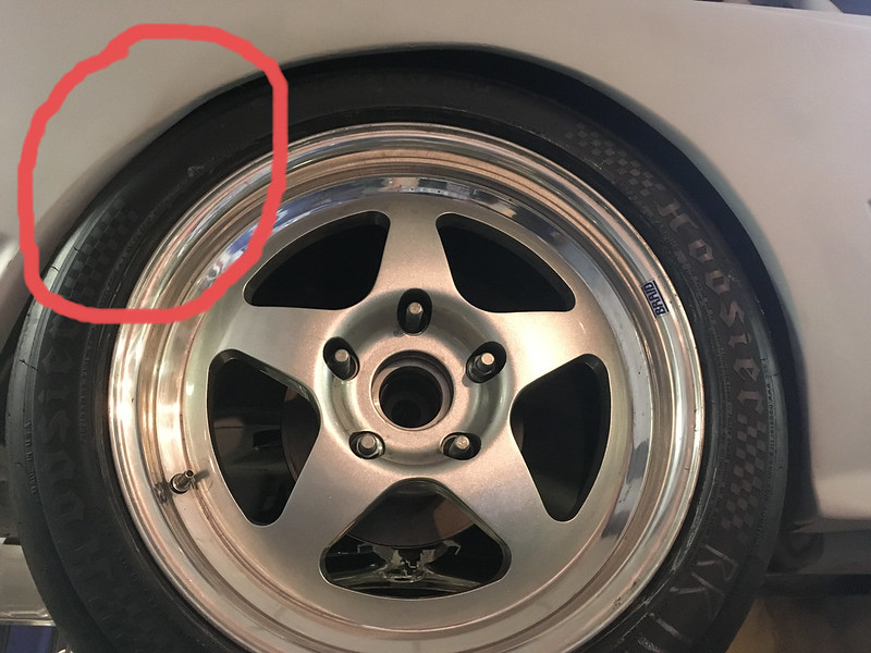
We’ve also seen that 205/65-15 rally tires (25”) will rub the underside of the spring perches but, fortunately, this customer’s car is already on coilovers.
So, by balancing a tire on the jack we were able to determine that the BFG tire would just fit inside the arch lip and go up inside the wheel house, if the offset were selected appropriately. ~ET22
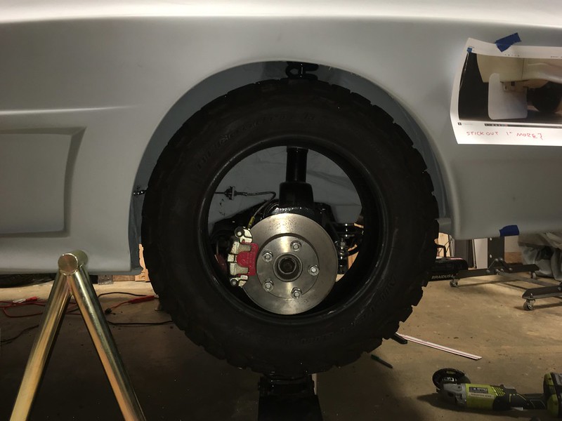
Then we remembered that our coffee table consists of four 225/55-17 (26.7”) tires on ET35 Allroad wheels and a glass top so we threw one of those on and it fit.
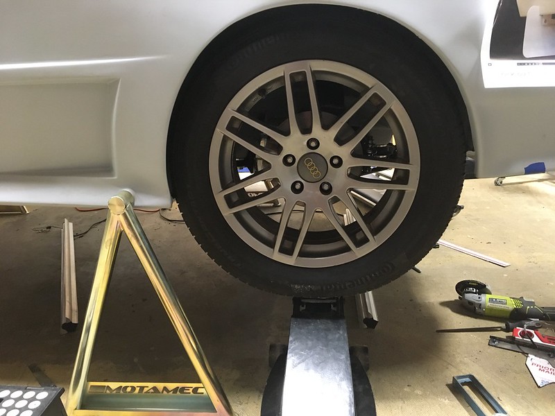
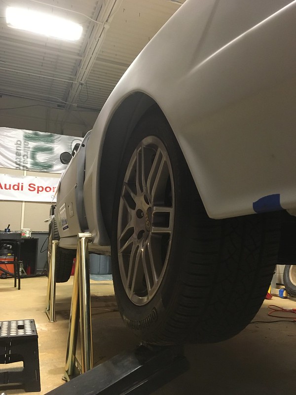
Then we tried it on the front:

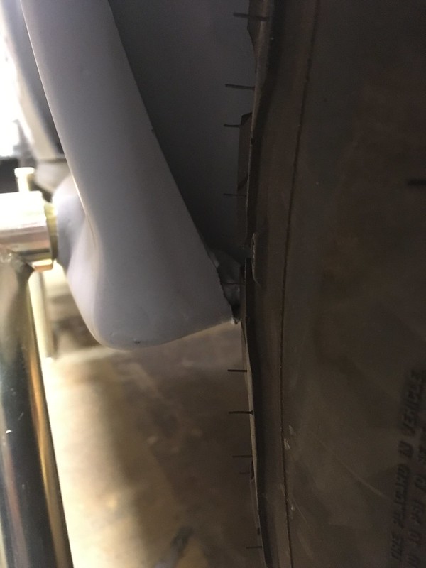
Unfortunately this proved even tighter than the rear, for a couple of reasons. Firstly, it rubbed on the tie rod ball joint.

and front and rear inner fenders at full lock and full compression. Rears first.
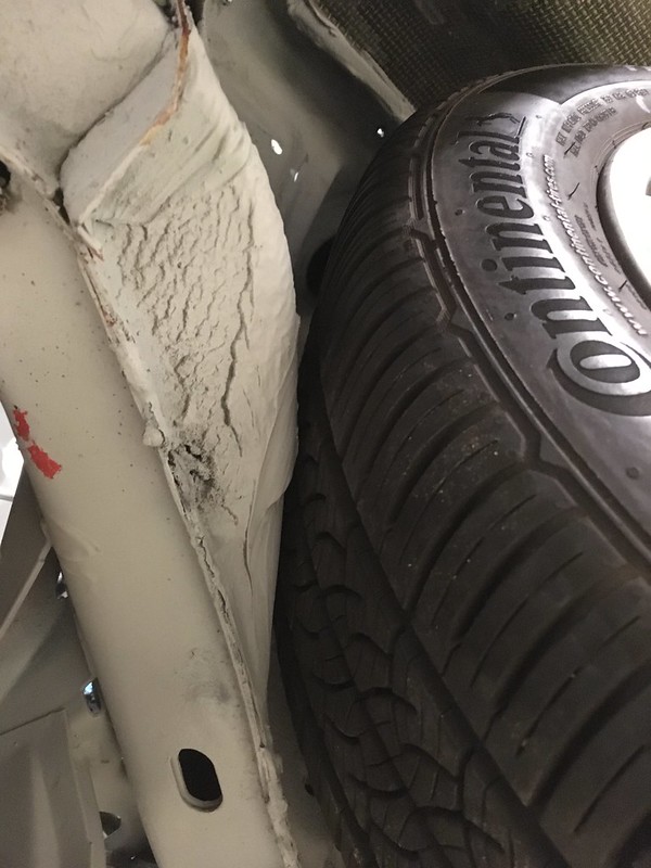
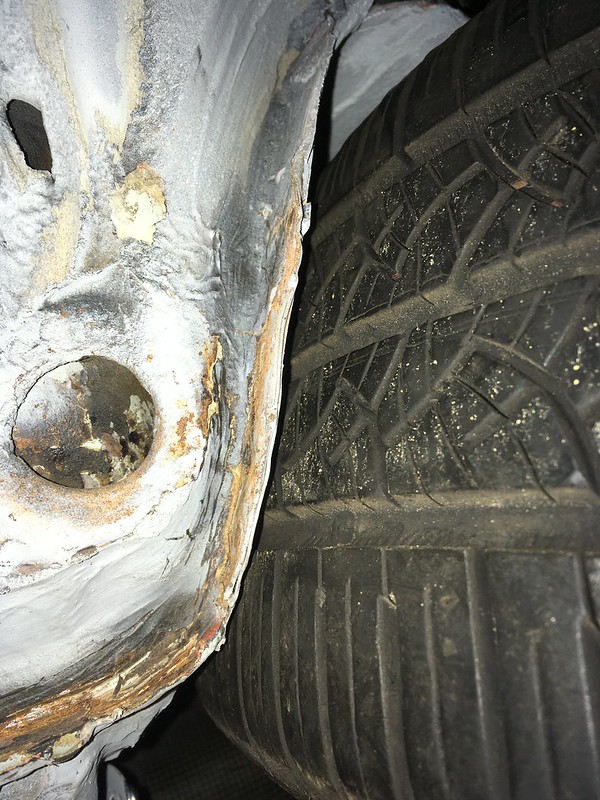
The ball joint is not a problem as this tire is 10mm wider than the AT tires being considered but it is also 8mm smaller diameter which means clearing the inner fenders is going to be impossible without hitting them with a BFH!
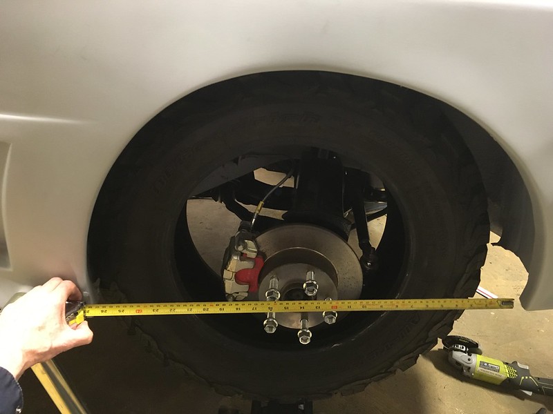
So what will fit? Turns out about 26.6” based on our jiggery-pokery.
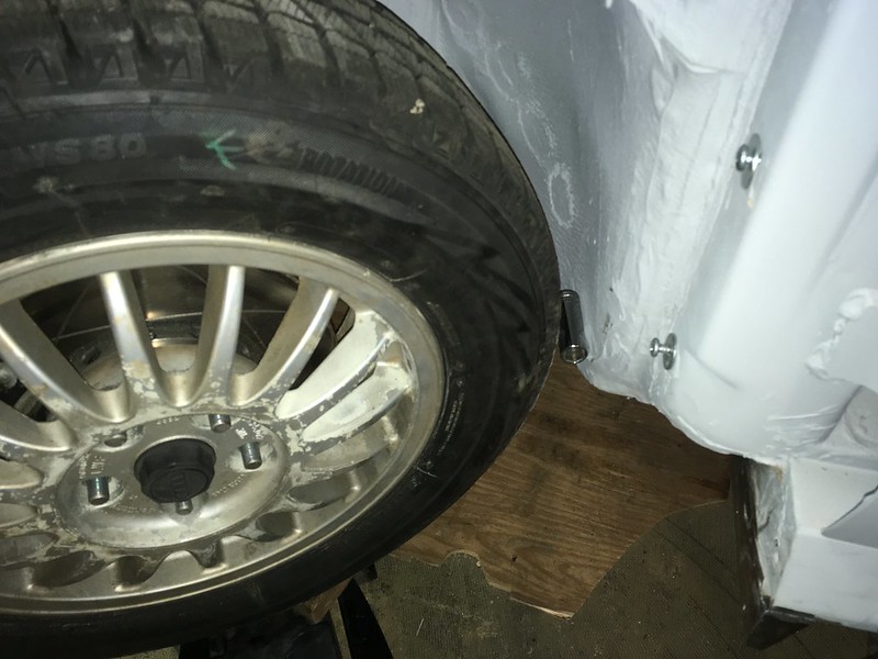
Yes, that’s a 25” 195/65-15 tire with a socket being used as a feeler gauge! Not very big but do bear in mind the OE tires were only 23.5” OD. Still, all is not lost. Yokohama make their excellent Geolander A/T G015 in 215/60-16 and it is “only” 26.1” OD. So this tire might be an option.
https://ytc-bm.s3.us-east-2.amazonaws.com/GEOLANDAR-A-T-G015-LT-3QL-Web.png?mtime=20201218225019&focal=none[/img]
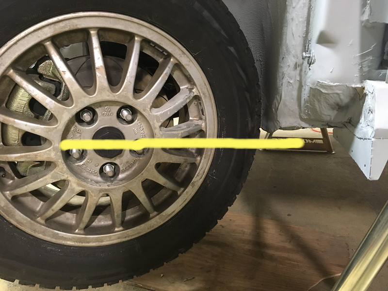
Still hopeful we could squeeze in the 215/65-16 we got creative. We investigated whether lifting the car would help. It is on coilovers after all. This is the 25” tire at full droop and, as you can see the center is about level with the bottom of the wheel house; the bit that rubs. So, unless you lift the car to the point that this is at full compression instead we don’t think a 27” tire will work.
Then we investigated if restricting the steering angle would help. With the small tire on we determined that full lock is about 28 degrees. Then, with the big tire on we found it doesn’t start to rub until about 22 degrees.
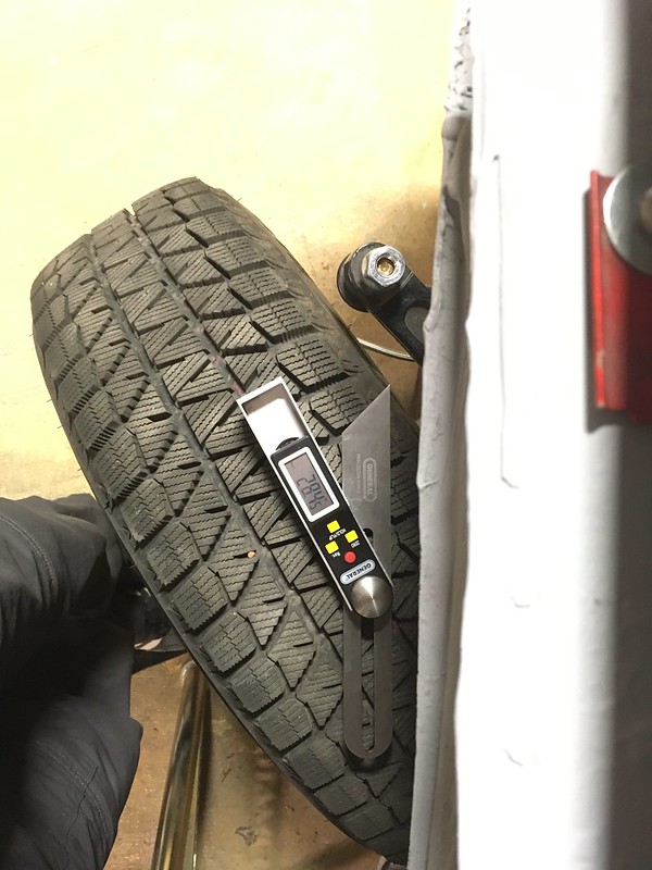
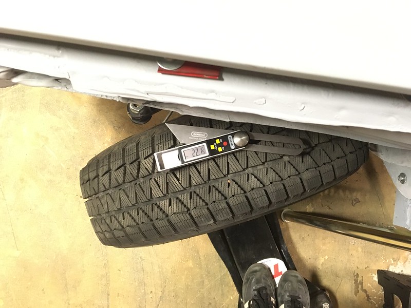
We are not sure if giving up 6 degrees of lock is a lot or how to restrict the rack but it might be a way forward. Alas, that is for someone else to figure out. We have a rally car to finish.


We were very curious because, you may remember, we had trouble fitting 275/40-17 Hosiers on the rear of ours. Not because of the width but because of the diameter which was only 25.7”. It seems the rear arches are very small so unless the chosen tire stays inside them they will impinge on the lip when travelling upwards. The BFG is 27”OD!

We’ve also seen that 205/65-15 rally tires (25”) will rub the underside of the spring perches but, fortunately, this customer’s car is already on coilovers.
So, by balancing a tire on the jack we were able to determine that the BFG tire would just fit inside the arch lip and go up inside the wheel house, if the offset were selected appropriately. ~ET22


Then we remembered that our coffee table consists of four 225/55-17 (26.7”) tires on ET35 Allroad wheels and a glass top so we threw one of those on and it fit.


Then we tried it on the front:

Unfortunately this proved even tighter than the rear, for a couple of reasons. Firstly, it rubbed on the tie rod ball joint.

and front and rear inner fenders at full lock and full compression. Rears first.


The ball joint is not a problem as this tire is 10mm wider than the AT tires being considered but it is also 8mm smaller diameter which means clearing the inner fenders is going to be impossible without hitting them with a BFH!
So what will fit? Turns out about 26.6” based on our jiggery-pokery.

Yes, that’s a 25” 195/65-15 tire with a socket being used as a feeler gauge! Not very big but do bear in mind the OE tires were only 23.5” OD. Still, all is not lost. Yokohama make their excellent Geolander A/T G015 in 215/60-16 and it is “only” 26.1” OD. So this tire might be an option.
https://ytc-bm.s3.us-east-2.amazonaws.com/GEOLANDAR-A-T-G015-LT-3QL-Web.png?mtime=20201218225019&focal=none[/img]
Still hopeful we could squeeze in the 215/65-16 we got creative. We investigated whether lifting the car would help. It is on coilovers after all. This is the 25” tire at full droop and, as you can see the center is about level with the bottom of the wheel house; the bit that rubs. So, unless you lift the car to the point that this is at full compression instead we don’t think a 27” tire will work.

Then we investigated if restricting the steering angle would help. With the small tire on we determined that full lock is about 28 degrees. Then, with the big tire on we found it doesn’t start to rub until about 22 degrees.


We are not sure if giving up 6 degrees of lock is a lot or how to restrict the rack but it might be a way forward. Alas, that is for someone else to figure out. We have a rally car to finish.

#112
PULL THE OTHER ONE!
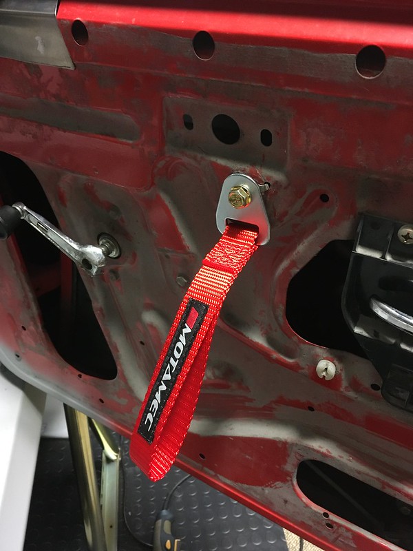
Ask any serious rally driver and they’ll tell you that it’s critical that your door pull straps match you pin stands. That’s why we bought these from MOTAMEC in the UK

We wanted to mount them in one of the holes for the original door pull handle because we knew that area of the door would be strong enough and it was in the right place. That had a twist bayonet type arrangement to it so we drilled it out and used our very high-end tool to install metric (of course) rivnuts.


They look even better with the snazzy cardboard door cards presented by Corbeau!
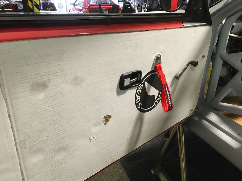
And finally, ask any serious rally driver and they’ll tell you that it’s critical that your door pull straps on your fridge match you pin stands. Guess we should have bought three!

Next week TIM uses a Hibnob as a steering wheel.

Ask any serious rally driver and they’ll tell you that it’s critical that your door pull straps match you pin stands. That’s why we bought these from MOTAMEC in the UK

We wanted to mount them in one of the holes for the original door pull handle because we knew that area of the door would be strong enough and it was in the right place. That had a twist bayonet type arrangement to it so we drilled it out and used our very high-end tool to install metric (of course) rivnuts.


They look even better with the snazzy cardboard door cards presented by Corbeau!

And finally, ask any serious rally driver and they’ll tell you that it’s critical that your door pull straps on your fridge match you pin stands. Guess we should have bought three!

Next week TIM uses a Hibnob as a steering wheel.

#113
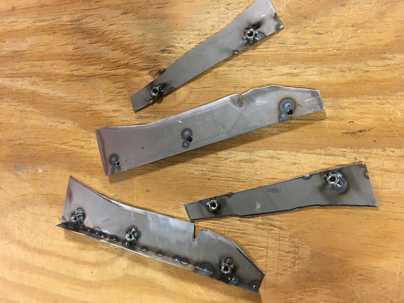
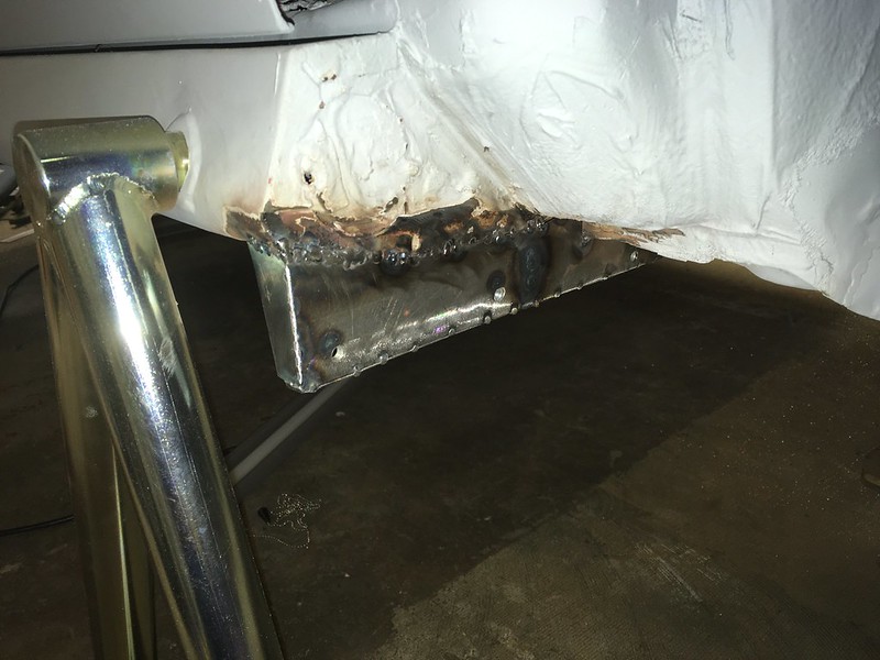
A continuation of our mud flap build... When we left off with mud flaps to go do some other stuff we had just finished making all the CAD templates for the brackets. Now we have formed them in steel, welded them to the car and even made an installed the actual mud flaps. Well, Sparco made them; we just trimmed them to fit.

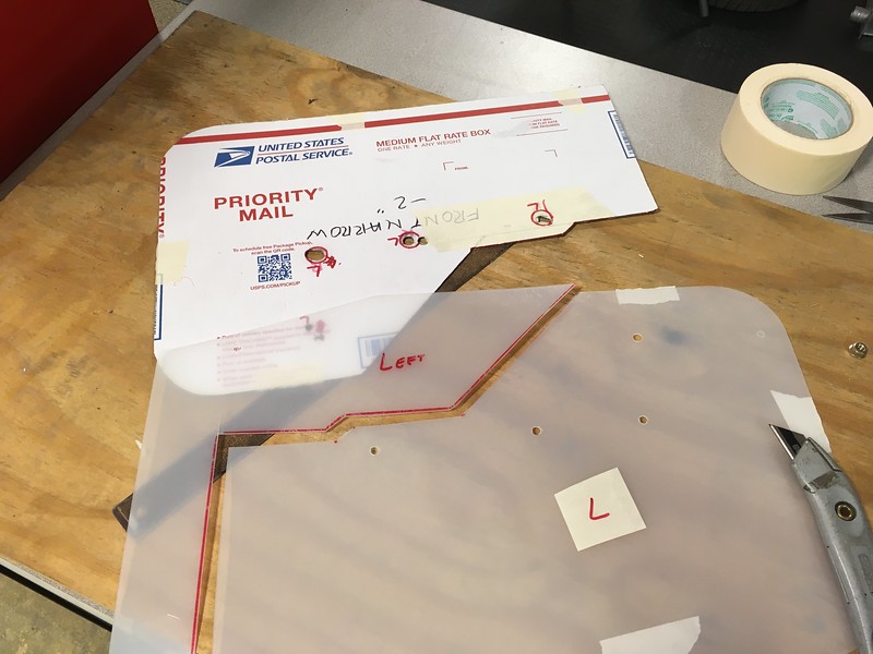

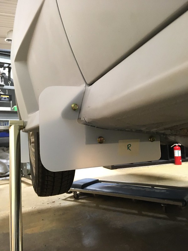
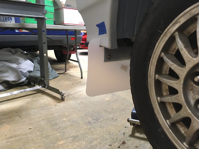
Next episode: footrests!


Next episode: footrests!

#114
"Rest Your Weary Feet" - Rally navigators need somewhere to plant their feet and brace themselves. So, rally cars have sturdy footrests. We could easily have bought a generic one or made a simple one but we’d seen the ones employed on the factory cars, and of course thought “we could make that”.

As usual we started with a cardboard model to get the shape similar and then transferred that to some 1/8” thick aluminium plate and the floor bracket to some steel.
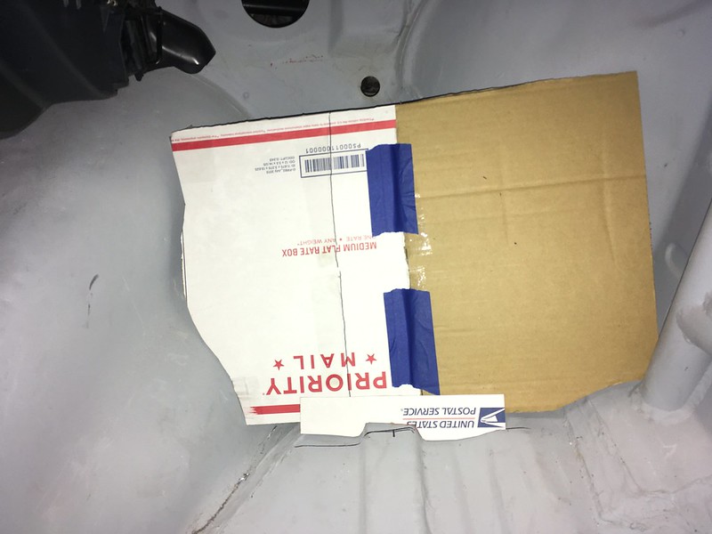

We then welded a bar of angle across the top and the plate to the floor at the angle we felt appropriate.

Then we started to work on the holes. We didn’t have dimple die punches even close to the size the works car used and they are not cheap. We scaled the original photos to see if we could measure them. They seemed to come out at 1-3/4”, which seemed huge so we went conservative and ordered a 1-1/4” punch.

Because we were using a smaller die, we altered the design a bit to include a few more holes which we made with a hole saw.
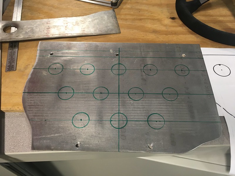

Then we dimpled them on the press.

We discovered that the process did distort the plate a bit but added a lot of strength. So much so that we couldn’t flatten it completely even using the press!


Not wanting to break it, we decided that it was flat enough and that the bracket would hold it at least a little flatter.
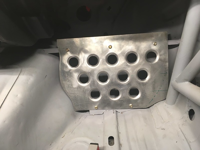
Finally, we trimmed off the excess and hit it with a wire wheel to remove some of the dimple die marks. We’re very pleased with the final result.
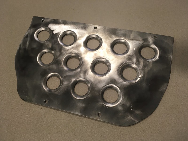
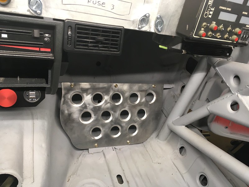
Next, we’ll attempt to reproduce the driver side foot rest.


As usual we started with a cardboard model to get the shape similar and then transferred that to some 1/8” thick aluminium plate and the floor bracket to some steel.


We then welded a bar of angle across the top and the plate to the floor at the angle we felt appropriate.

Then we started to work on the holes. We didn’t have dimple die punches even close to the size the works car used and they are not cheap. We scaled the original photos to see if we could measure them. They seemed to come out at 1-3/4”, which seemed huge so we went conservative and ordered a 1-1/4” punch.

Because we were using a smaller die, we altered the design a bit to include a few more holes which we made with a hole saw.


Then we dimpled them on the press.

We discovered that the process did distort the plate a bit but added a lot of strength. So much so that we couldn’t flatten it completely even using the press!


Not wanting to break it, we decided that it was flat enough and that the bracket would hold it at least a little flatter.

Finally, we trimmed off the excess and hit it with a wire wheel to remove some of the dimple die marks. We’re very pleased with the final result.


Next, we’ll attempt to reproduce the driver side foot rest.

#115
Driver's Footrest: In case there’s a long straight between corners or for transits we thought we should have a nice foot rest for our clutch foot. Of course, we tried to reproduce the one on the factory cars because buying a perfectly good off the shelf one would make too much sense. First some auto CAD:
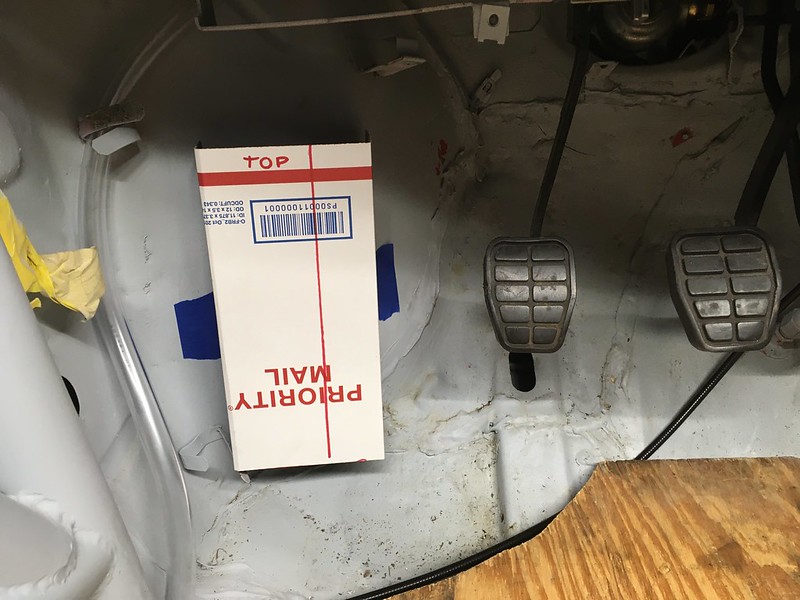
Followed by some 1/8” aluminium, with dimple holes:

Then we cut it and welded it at what we thought was the appropriate angles. It’s just tack welded for now in case we don’t know what we’re doing.

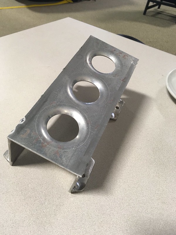
Then we temporarily fastened it in place with some self-tappers. These will be replaced with rivnuts once the shell is painted.
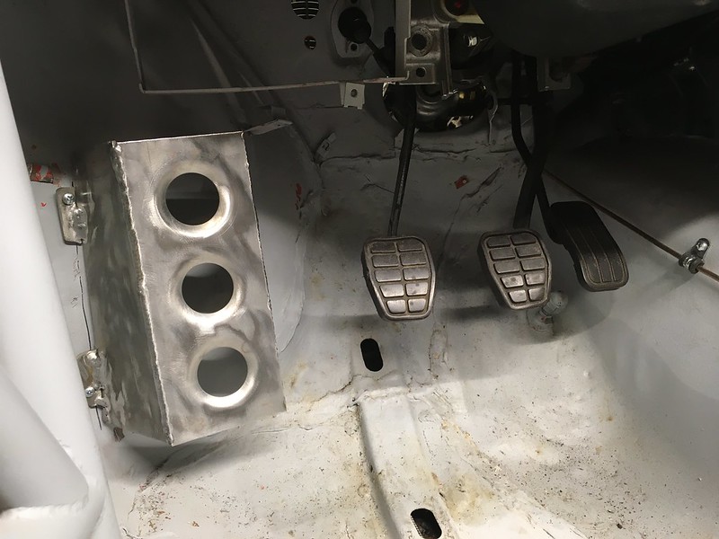


Followed by some 1/8” aluminium, with dimple holes:

Then we cut it and welded it at what we thought was the appropriate angles. It’s just tack welded for now in case we don’t know what we’re doing.


Then we temporarily fastened it in place with some self-tappers. These will be replaced with rivnuts once the shell is painted.


#116
What’s this called? The Audi parts diagrams call it a “stop buffer” but what does it stop? Engine pitch perhaps? Well, it’s probably important so we should have one, exactly like the works cars of course. Oh boy! We’ll call it an Engine Pitch Stop or EPS.

It sits in a receptacle on the bumper bar and presumably stops the engine from pitching back and forth. Subarus have one on the bulkhead. We bought a performance one from ECS because who doesn’t want a big red *** sticking out of the front of their engine, even if it is mounted on a piece of PVC conduit!

We did intend to mount ours on the right side of the engine like the factory cars and even designed a mounting plate for it but then we realized it might be a bit complicated to design an alternator bracket in combination with this so decided to put it on the left side instead. It helped that there were two threaded holes in exactly the right place.
The EPS fits in a cup welded to the bumper bar so we needed to mock that up. Fortunately, we discovered that most paint can lids are the right size so a can of Rustoleum Self Etching Primer donated its lid. This intersects with the bumper bar about half way so we had to shape it carefully with a file.

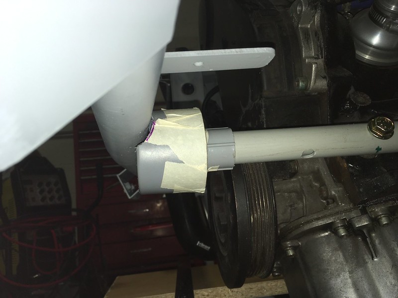
It also changed color during the process because of, well, fail. Undaunted we acquired some steel tubes in the appropriate diameters and proceeded to recreate our plastic EPS in metal. First attempt was a little long.
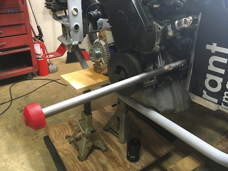
That’s much better.
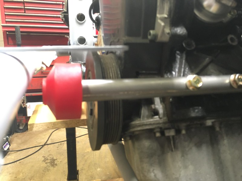
Now for the tricky bit.

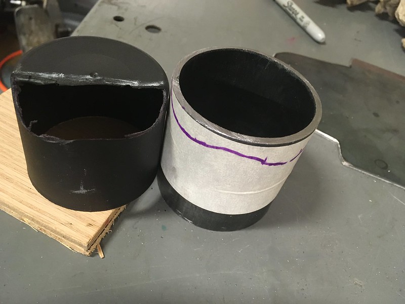

After about four days of filing, we had a fit. The cup fit on the bumper bar too.


Happy with the way it looked we cut it to length, welded it up, added a brace and stood back and admired it.

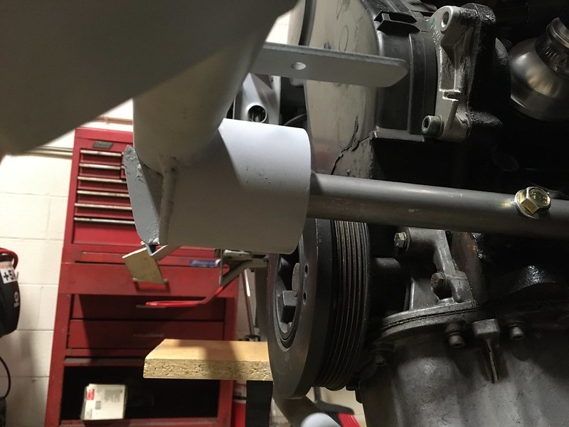
Can’t wait till its gold zinc plated.


It sits in a receptacle on the bumper bar and presumably stops the engine from pitching back and forth. Subarus have one on the bulkhead. We bought a performance one from ECS because who doesn’t want a big red *** sticking out of the front of their engine, even if it is mounted on a piece of PVC conduit!

We did intend to mount ours on the right side of the engine like the factory cars and even designed a mounting plate for it but then we realized it might be a bit complicated to design an alternator bracket in combination with this so decided to put it on the left side instead. It helped that there were two threaded holes in exactly the right place.
The EPS fits in a cup welded to the bumper bar so we needed to mock that up. Fortunately, we discovered that most paint can lids are the right size so a can of Rustoleum Self Etching Primer donated its lid. This intersects with the bumper bar about half way so we had to shape it carefully with a file.


It also changed color during the process because of, well, fail. Undaunted we acquired some steel tubes in the appropriate diameters and proceeded to recreate our plastic EPS in metal. First attempt was a little long.

That’s much better.

Now for the tricky bit.


After about four days of filing, we had a fit. The cup fit on the bumper bar too.


Happy with the way it looked we cut it to length, welded it up, added a brace and stood back and admired it.


Can’t wait till its gold zinc plated.

#117
Time To Get In The Groove
It recently occurred to us that if we ever get to drive this thing we might get a flat and need a spare tire. But what size and where to put it? The stock spare is a skinny donut that fits in the trunk up against the left quarter panel. Our car didn’t come with one and we doubt we’d wanna use a 35+ year old skinny tire anyway. No, we require something a bit more road worthy if not stage worthy.
This is also complicated by the fact that we will be running two very different sizes of tire on the car. 195/65-15 gravel rally tires and snow tires and 23/59-15 tarmac rally tires. While we don’t feel the need to carry an exact match we would like something at least a similar overall diameter. Unfortunately the gravel ties is 25” OD while the tarmac tire is only 23”! And we’ll need a suitable wheel.
There a lot of 195/60-15 tires on the market at 24.2” and a few 225/50-15 at 23.9” OD. Perhaps one of these would be the sweet spot. We also have a set of original 15x6 Quattro wheels we could mount one of these on. Well, the 195 anyway. 225 might be a stretch. Oh, did we mention, we’d also like to carry our emergency tool kit as well?
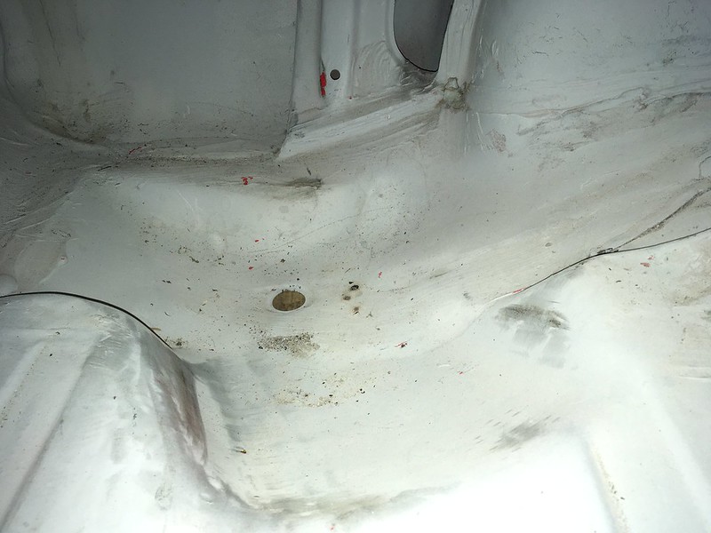
Now, where to store it. Well it turns out that nothing much bigger than the OE donut will fit in the original location so that’s out. However, since we removed the US spec bumper extensions from inside the truck we do now have access to this angled groove in the trunk floor. We thought it was to aid getting the donut into place but now we are thinking it may have been intended for a full size spare all along, at least till they got too wide for one.
Here’s a picture of the groove:
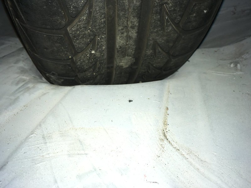
Let’s see what can get in the groove man! 215? Yes.
195/65 won’t fit in the spare’s location:
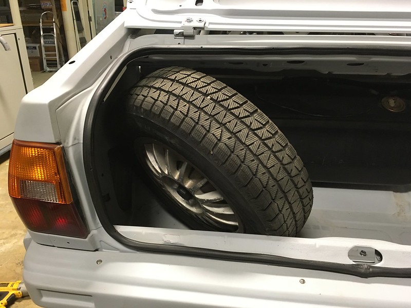
But will get in the groove dude:

225? Nah, not really but could be made to work:

195 and toolbox getting in the grove:
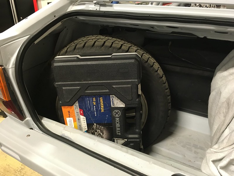
TB5 in the groove. Nah, don’t be silly. Fits in the trunk though, just:
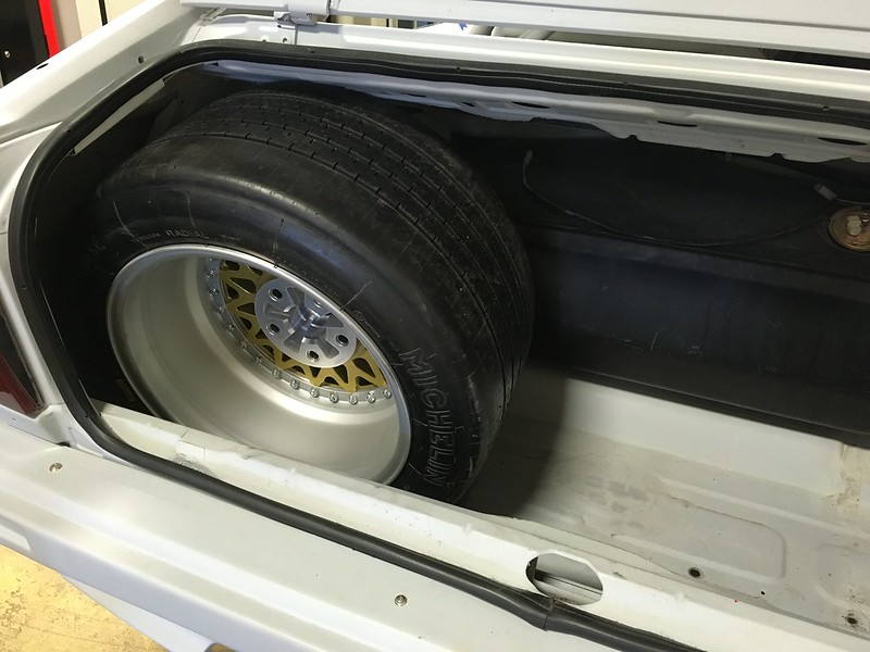
So still not finalized and we’ll still have to figure out how to secure it. Now, back to more serious matters.

It recently occurred to us that if we ever get to drive this thing we might get a flat and need a spare tire. But what size and where to put it? The stock spare is a skinny donut that fits in the trunk up against the left quarter panel. Our car didn’t come with one and we doubt we’d wanna use a 35+ year old skinny tire anyway. No, we require something a bit more road worthy if not stage worthy.
This is also complicated by the fact that we will be running two very different sizes of tire on the car. 195/65-15 gravel rally tires and snow tires and 23/59-15 tarmac rally tires. While we don’t feel the need to carry an exact match we would like something at least a similar overall diameter. Unfortunately the gravel ties is 25” OD while the tarmac tire is only 23”! And we’ll need a suitable wheel.
There a lot of 195/60-15 tires on the market at 24.2” and a few 225/50-15 at 23.9” OD. Perhaps one of these would be the sweet spot. We also have a set of original 15x6 Quattro wheels we could mount one of these on. Well, the 195 anyway. 225 might be a stretch. Oh, did we mention, we’d also like to carry our emergency tool kit as well?
Now, where to store it. Well it turns out that nothing much bigger than the OE donut will fit in the original location so that’s out. However, since we removed the US spec bumper extensions from inside the truck we do now have access to this angled groove in the trunk floor. We thought it was to aid getting the donut into place but now we are thinking it may have been intended for a full size spare all along, at least till they got too wide for one.
Here’s a picture of the groove:

Let’s see what can get in the groove man! 215? Yes.

195/65 won’t fit in the spare’s location:

But will get in the groove dude:

225? Nah, not really but could be made to work:

195 and toolbox getting in the grove:

TB5 in the groove. Nah, don’t be silly. Fits in the trunk though, just:

So still not finalized and we’ll still have to figure out how to secure it. Now, back to more serious matters.

#118
We’ve been frustrated by the rear muffler just hanging around but finally had some time to tackle it. We wanted to replicate the works cars even though it’s ridiculously over built.
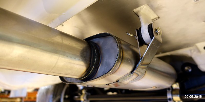
How hard could it be? First find some bushings from McMaster and some cardboard:

Guess the length and reproduce it in stainless:


Then weld it to the car:

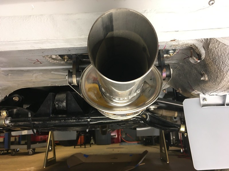
Actually, it’s screwed to the car for now. We’ll weld it once we get the car upside down.


How hard could it be? First find some bushings from McMaster and some cardboard:

Guess the length and reproduce it in stainless:


Then weld it to the car:


Actually, it’s screwed to the car for now. We’ll weld it once we get the car upside down.

#119
ALTERNATOR-TIVE UNIVERSE
We all know that Audis are different and UR Quattros even more different. Well, we also tend to do things differently and that did not change when it came to installing the alternator for our rally car.
We could have just used the stock alternator in the stock location on the stock bracket but that meant it wouldn’t be able to power our ridiculous number of lights, it would be right in front of the radiator and, after removing the power steering pump, be hanging on the end of a foot long appendage that just looked silly. So we said, “Let’s do something different”.
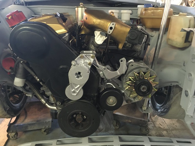
So we did two things. We found a relatively inexpensive 200 amp Ford alternator from a local supplier and we decided we could move the engine pitch stop to the left side of the engine. This meant we could mount the alternator on the right side of the engine with a custom bracket.
[img]https://live.staticflickr.com/65535/...3147db6d_c.jpg[/img]
Now some of you are probably saying, ”Why didn’t you just use a bracket from an Audi that had the alternator on the right side of the engine?” Well, we could do that but Audi didn’t use Ford alternators did they? Custom bracket it was then. How do you do that? You might ask. So did we!
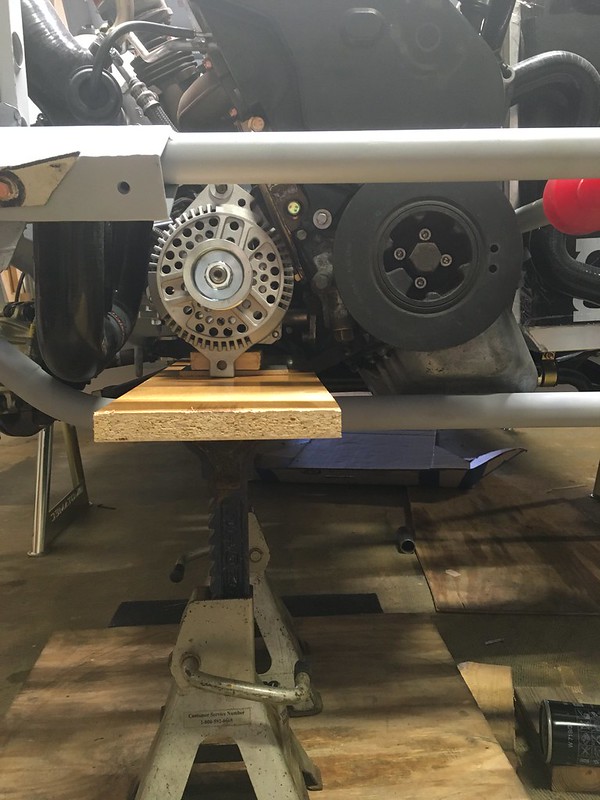
We started with a CAD template, of course.

Which we cunningly fashioned into a front bracket looking thingy.
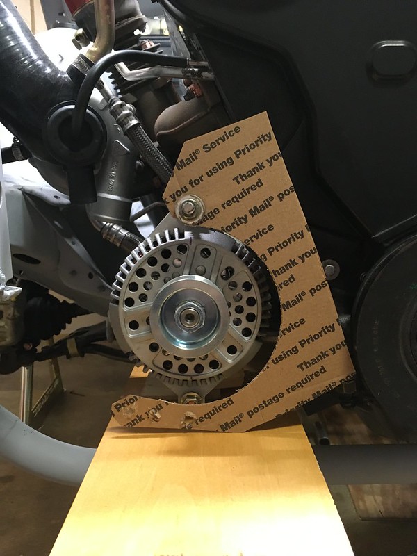
Then we made a base plate that would bolt to some existing holes on the block

Then taped the two together
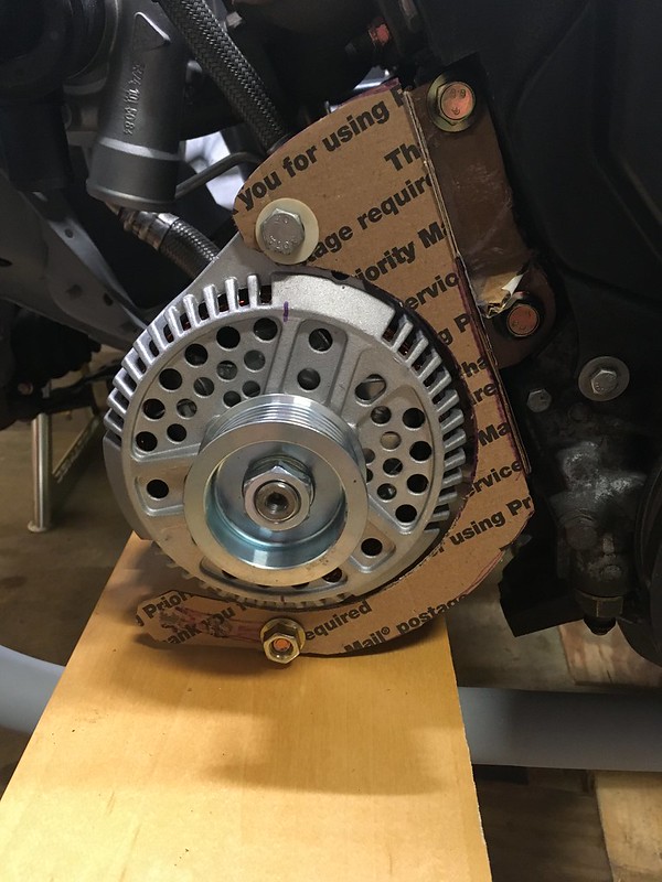
Once we were happy with the design, we cut the pieces out of 3/16” and 1/8” steel plate.

In order to ensure (hopefully) that the two pullies were lined up in every conceivable axis we decided to clamp them together using a very stiff piece of angle iron before welding everything up. This seemed to work, much to our surprise. And yes, we checked, with measury things.


Then came the tricky bit: Finding a belt the right length.

Piece of cake (actually, we prefer Hobnobs thank you)

We all know that Audis are different and UR Quattros even more different. Well, we also tend to do things differently and that did not change when it came to installing the alternator for our rally car.
We could have just used the stock alternator in the stock location on the stock bracket but that meant it wouldn’t be able to power our ridiculous number of lights, it would be right in front of the radiator and, after removing the power steering pump, be hanging on the end of a foot long appendage that just looked silly. So we said, “Let’s do something different”.

So we did two things. We found a relatively inexpensive 200 amp Ford alternator from a local supplier and we decided we could move the engine pitch stop to the left side of the engine. This meant we could mount the alternator on the right side of the engine with a custom bracket.
[img]https://live.staticflickr.com/65535/...3147db6d_c.jpg[/img]
Now some of you are probably saying, ”Why didn’t you just use a bracket from an Audi that had the alternator on the right side of the engine?” Well, we could do that but Audi didn’t use Ford alternators did they? Custom bracket it was then. How do you do that? You might ask. So did we!

We started with a CAD template, of course.

Which we cunningly fashioned into a front bracket looking thingy.

Then we made a base plate that would bolt to some existing holes on the block

Then taped the two together

Once we were happy with the design, we cut the pieces out of 3/16” and 1/8” steel plate.

In order to ensure (hopefully) that the two pullies were lined up in every conceivable axis we decided to clamp them together using a very stiff piece of angle iron before welding everything up. This seemed to work, much to our surprise. And yes, we checked, with measury things.


Then came the tricky bit: Finding a belt the right length.

Piece of cake (actually, we prefer Hobnobs thank you)

Last edited by team illuminata; 11-04-2021 at 09:21 AM.
#120
Committing to Front Bars
The last time we referenced the front skid plate bar was back in May when we were installing the front tow hook which is sandwiched between the chassis rail and the skid plate bar mounting flange. At that time, it was mocked up from PVC conduit. Now we felt it was time to commit it to steel and even connect it to the front bumper bar. How hard could that be?
Pretty tricky actually. We don’t have a pipe bender but have access to one but it would be a one shot deal. However, it proved difficult to make the compound bends in the same plane and end up with the bar at the correct length. When we got it back to the workshop what we had was a wrong length bar with a 90 degree bend at each end! Both bends were in the same plane but, as you will see, that didn’t matter in the end. It was a bit disappointing to be honest so we put the kettle on and had a think over some Yorkshire Tea and Hobnobs. They did the trick as by the last sip and crumb it dawned on us that we had all the right pieces, just not necessarily in the right order! If we chopped up the continuous 90 bends we could configure them in the right way and make the bar any length we wanted and we wanted it the correct length. So that’s what we did.


We even got it to “make the noise” (be level if you’re watching in black and white)

The next part of the project was to connect the skid plate bar to the bumper bar with a couple of brace bars in such a way that either bar could be removed separately. Fortunately, we had a model for this from MAT’s restoration, which we are not copying in any way shape or form, honestly.

So, we squished some pipe:

It took ages to grind the correct angle on the top but once we were happy with it we tacked the braces in place with the bars in situ:

Then a few issues revealed themselves. Firstly, the right-side brace bar interferes with the intercooler inlet pipe so that will need to be modified

But also, and more fundamentally, we couldn’t remove either bar from the car! We were perplexed for a few minutes as we had the configuration just like the MAT restoration bars but then we realized we had mounted our bars with studs and nuts and they had uses bolts! Once we removed the studs from the bumper bar flanges it fell away elegantly. We will be attaching it with bolts from now on. DUH!
So here are the two bars tacked together and removed and primed later.


We’d like to see a Norwegian Blue muscle up to these bars and try to bend them apart with its little pecker!

The last time we referenced the front skid plate bar was back in May when we were installing the front tow hook which is sandwiched between the chassis rail and the skid plate bar mounting flange. At that time, it was mocked up from PVC conduit. Now we felt it was time to commit it to steel and even connect it to the front bumper bar. How hard could that be?
Pretty tricky actually. We don’t have a pipe bender but have access to one but it would be a one shot deal. However, it proved difficult to make the compound bends in the same plane and end up with the bar at the correct length. When we got it back to the workshop what we had was a wrong length bar with a 90 degree bend at each end! Both bends were in the same plane but, as you will see, that didn’t matter in the end. It was a bit disappointing to be honest so we put the kettle on and had a think over some Yorkshire Tea and Hobnobs. They did the trick as by the last sip and crumb it dawned on us that we had all the right pieces, just not necessarily in the right order! If we chopped up the continuous 90 bends we could configure them in the right way and make the bar any length we wanted and we wanted it the correct length. So that’s what we did.


We even got it to “make the noise” (be level if you’re watching in black and white)

The next part of the project was to connect the skid plate bar to the bumper bar with a couple of brace bars in such a way that either bar could be removed separately. Fortunately, we had a model for this from MAT’s restoration, which we are not copying in any way shape or form, honestly.

So, we squished some pipe:

It took ages to grind the correct angle on the top but once we were happy with it we tacked the braces in place with the bars in situ:

Then a few issues revealed themselves. Firstly, the right-side brace bar interferes with the intercooler inlet pipe so that will need to be modified

But also, and more fundamentally, we couldn’t remove either bar from the car! We were perplexed for a few minutes as we had the configuration just like the MAT restoration bars but then we realized we had mounted our bars with studs and nuts and they had uses bolts! Once we removed the studs from the bumper bar flanges it fell away elegantly. We will be attaching it with bolts from now on. DUH!
So here are the two bars tacked together and removed and primed later.


We’d like to see a Norwegian Blue muscle up to these bars and try to bend them apart with its little pecker!


